|
1
|
|
|
2
|
- The EZ-Comp System automatically corrects for tool wear and other process
deviations by transmitting measured values directly into the CNC offset
tables!
- This makes The EZ-Comp System an
invaluable tool in CNC productivity.
|
|
3
|
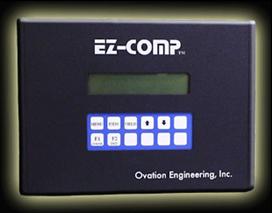
- The Ovation Engineering EZ-Comp Programmable Tool Compensation Interface
helps to eliminate machine down time and part size errors due to
manually entered tool offset data by automatically transferring tool
offset data into the CNC control’s offset tables. Data can be collected and processed
from a variety of gaging devices and SPC software packages.
|
|
4
|
- The EZ-Comp collects data in real time from a gaging device or SPC
software. It then calculates a statistical or fixed running average for
each controlled feature and compares the average to user programmed tool
compensation limits. If the average exceeds the limit, the required tool
receives a compensation.
|
|
5
|
- The system is capable of providing offset data for up to 20 measured
features. Each feature will correspond to a channel in the EZ-Comp. The
size control for each of these features is accomplished by automatically
changing tool offset values in the CNC control. The EZ-Comp interfaces to the
machine's controller through either an RS-232 serial port or parallel
I/O.
|
|
6
|
- Automatic tool compensation allows the operator to focus on tasks other
than entering offset data into the control. It also eliminates the
possibility of entering erroneous data, or transposing data values
(i.e., .0051 instead of .0015) In addition, the EZ-Comp makes
compensation decisions based upon a running average, as opposed to
single part measurements. This provides for a much more stable response
to variation by providing a “filtering” effect on the data. The result
is that small, “normal” , erratic, and unpredictable variations in the
process are ignored, while large and consistent variations (such as tool
wear) are compensated.
|
|
7
|
- Upper and Lower Tool Compensation Limits
- Comp Target
- Max Comp
- Skip
- Trend
- Direction
- Upper and Lower Reject Limits
- Tool Compensation Algorithm
|
|
8
|
- The Upper & Lower Tool Compensation limits are values that are
programmed on a per tool basis. The Upper & Lower Tool Compensation
limits determine the process level (running average) that must be
reached before an offset will be sent to the CNC. This parameter is usually expressed as
deviation from mean. If the
process running average is within these limits, no compensation will be
sent on the current cycle.
|
|
9
|
- This is the process target value.
This parameter is used to anticipate process trends by
compensating to a value other than the mean. Set this parameter to the desired
process level to be reached on each comp. This parameter is usually
expressed as deviation from mean. To target the mean, set this parameter
to zero. The EZ-Comp uses a default value of +0.0000
|
|
10
|
- This is the maximum amount of compensation that can be sent on any given
cycle. If the calculated comp amount exceeds this value, the
compensation that sent will be equal to the Max comp value. If the Max
Comp value hasn’t been programmed, the EZ-Comp uses a default value,
which is based on the setting of the resolution parameter. (The Max Comp
cannot exceed the comp range of the system.)
|
|
11
|
- This value represents the number of parts that exist in the queue
between the operation creating the compensated feature and the gage that
is measuring the compensated feature. This value specifies how many
parts will be gaged after a compensation, before the first part affected
by the comp will reach the gage.
Set this parameter to a value greater than zero if
non-compensated parts will reach the gage after a compensation is
sent. The default value for this
parameter is zero.
|
|
12
|
- This value indicates the number of gage readings used to calculate the
running average. The EZ-Comp uses
a default value of 1.
|
|
13
|
- This parameter determines whether the sign of the calculated
compensation value will be reversed before being transmitted to the CNC
offset tables. Normally the comp
sign will be the opposite of the calculated trend in order to correct
the process back toward the mean.
The default value is POS (Positive). If the unit is compensating in the
wrong direction change this parameter to NEG (Negative). Negative Comp
direction is often necessary when a cut-off tool is compensated to
control part length.
|
|
14
|
- Data received from the gage that is outside of these limits will not be
used in the compensation algorithm.
|
|
15
|
- The EZ-Comp software uses
exclusive algorithms for calculating the current process level
after every gaging cycle. This process level is compared to the
programmed tool comp limits for making comp decisions. If the calculated process level
exceeds one of the comp limits, an offset is sent to the CNC control
such that the process will be brought back to the mean or the programmed
target level.
|
|
16
|
- The interface between the EZ-Comp, the machine tool, and the gage may be
achieved by a variety of different methods. The installation
technician will determine the
optimum method for the type of CNC and gage system being used.
|
|
17
|
- Once installed, the EZ-Comp
System begins to generate automatic offsets. This starts the cycle of creating
and maintaining a useable product
based on specific work piece tolerances.
All of this is done so efficiently that the benefits of the EZ-Comp
System will be recognized immediately.
|
|
18
|
- The EZ-Comp System saves you time, labor, and materials. Stop throwing money away
- CALL US TODAY!
|
 Notes
Notes